- 1.5 Gbps high speed data transmission
- Bidirectional 1 Mbps low speed data transmission
- DC12V/15W non-contacting power supply


![]()
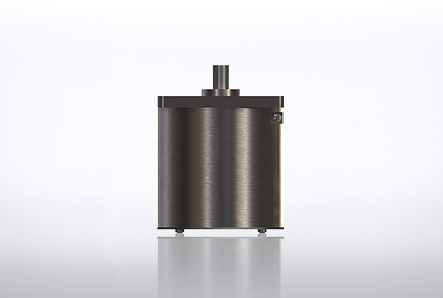
RLC-3-55-1.5G is capable of maximum 1.5 Gbps signal transmission (unidirectional 1ch) from the rotor side to the stator side and up to 1 Mbps bidirectional signal transmission between the rotor side and stator side.
It is also capable of non-contacting signal transmission and non-contacting power supply (12V/15W) and permits 360-degree continuous rotation communication with a rotating body.
The channel for ultra-high-speed data transmission covers the transmission band of HD-SDI signals (SMTPE-292M). The low-speed data are bidirectional signals, so the product can be used for serial data transmission (RS232C, RS422, etc.) for controls.
![]()
| Interface | |
|---|---|
| Low-speed data transmission | bidirectional 1ch STATOR ⇔ ROTOR |
| Ultra-high-speed data transmission | unidirectional 1ch ROTOR → STATOR |
| Power-supply voltage | DC12V±5% |
| Performance | |
|---|---|
| Low-speed data transmission rate | - 1Mbps |
| Ultra-high-speed data transmission rate | 155Mbps - 1.5Gbps |
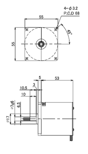
| Mechanical features | |
|---|---|
| Rotation speed | <100rpm |
| Dimensions (dia. xh) (mm) | 55×58 (excl. the center shaft) |
| Weight | <300g |
| Environmental features | |
|---|---|
| Temperature range | -20 / +60 degC |
| Vibration | 10Hz to 2KHz 147m/s² |
| Shock | 294m/s² 11ms |
![]()
| # | Color | Symbol | Description | Lead Wire |
|---|---|---|---|---|
| 1 | White | SG | Signal Ground | UL AWG28 |
| 2 | Blue | CH1_OUT | Signal 2_Output(3.3V-LVCMOS) | UL AWG28 |
| 3 | White | SG | Signal Ground | UL AWG28 |
| 4 | Red | CH2_IN | Signal 1_Input(3.3V-LVCMOS) | UL AWG28 |
| 5 | Yellow | +12V_IN | +12V_Input | UL AWG28 |
| 6 | Black | GND | Power Ground | UL AWG28 |
| 7 | White | Tx+ | CML Output+ | U.FL-2LP-04(Hirose) Impedance 50ohms |
| 8 | White | Tx- | CML Output- |
| # | Color | Symbol | Description | Lead Wire |
|---|---|---|---|---|
| 1 | Brown | GND | Ground | UL AWG28 |
| 2 | Orange | +3.3V DC | +3.3V/20mA(for Error indicator) | UL AWG28 |
| 3 | Gray | Fault | Error Output | UL AWG28 |
| 4 | Green | Tx_Disable | RLC internal circuit reset line | UL AWG28 |
| 5 | White | SG | Signal Ground | UL AWG28 |
| 6 | Blue | CH2_OUT | Signal 2_Output(3.3V-LVCMOS) | UL AWG28 |
| 7 | White | SG | Signal Ground | UL AWG28 |
| 8 | Red | CH1_IN | Signal 1_Input(3.3V-LVCMOS) | UL AWG28 |
| 9 | Yellow | +12V_OUT | +12V_Output | UL AWG28 |
| 10 | Black | GND | Power Ground | UL AWG28 |
| 11 | White | Rx+ | CML Input+ | U.FL-2LP-04(Hirose) Impedance 50ohms |
| 12 | White | Rx- | CML Input- |