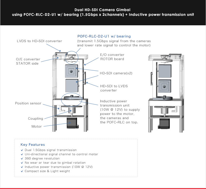
- Dual Channels of 1.5G hi-data rate signal link
- Single lower data rate signal channel
- Compact size & Light weight

![]()
- ・Dual channels of 1.5G high data rate signal transmission are suitable for multi sensor solutions such as surveillance/security systems.
- ・A single lower data rate signal channel can be used for controlling signal transmission.
- ・Durable in harsh environments. (see specifications)
![]()
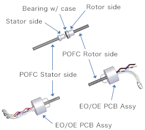
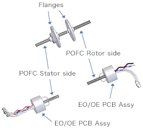
| Single bearing | w/o bearing | double bearings |
|---|---|---|
 |
 |
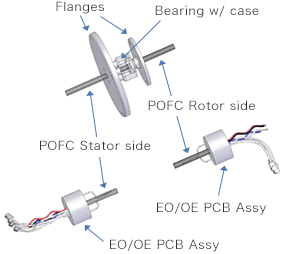 |
| "The single bearing POFC-D2-U1" has its signal path coupling inside the bearing. Customers can integrate the unit into their structures to make a rotational signal transmission joint. |
"The bearingless POFC-D2-U1" is designed to be integrated into customers' bearings. Depending on the size of the bearings, we can offer different unit sizes for the right fit. | "The double bearing POFC-D2-U1" can be used when there is an existing bearing in customers' structures. The POF-Coupling unit can be integrated into such structure without disturbing the functionality of the two bearings, yet giving it a rotational signal transmission joint . |
| Electrical characteristics | |
|---|---|
| High speed signal transmission channel | 1.5Gbps Uni-directional 2 channels (Rotor ⇒ Stator) |
| Low speed signal transmission channel | 38.4Kbps Uni-directional 1 channel (Stator ⇒ Rotor) |
| Power input (*1) | +3.3V +/-5% |
| Mechanical characteristics | POFC-D2-U1 w/ bearing | POFC-D2-U1 w/o bearing | POFC-D2-U1 double bearings |
|---|---|---|---|
| Dimensions(dia.x h) & Weight (Optical Rotary Joint) | φ8 x 4.5/16g | φ23 x 25(MAX)/21g | φ23 x 25(MAX)/21g |
| Dimensions(dia.x h) & Weight (EO/OE PCB Assy) | φ16 x 10(x2) | ||
| Load limitation to the bearings | Thrust load: 9.8N(MAX) | Not specified (*3) | Not specified (*3) |
| Rotation speed(rpm) | 100rpm | ||
| Environmental | |
|---|---|
| Temperature range | -40/+85deg C |
| Vibration resistance | 10Hz - 2000Hz 147m/s² |
| Shock resistance | 294m/s² 11ms |
(*1) The power for RLC® is required at the rotor side and the stator side.
(*2) Diameter may differ depending on frame thickness.
(*3) Depending on customer bearings' characteristics.
(*4) For faster rotation speed, please consult our customer support.
![]()
| # | Color | Symbol | Description | Cablespec. |
|---|---|---|---|---|
| 1 | Yellow | GND | Ground | UL AWG30 |
| 2 | Black | +3.3V_IN | +3.3V Input | UL AWG30 |
| 3 | White | SG | Low data rate signal Ground | UL AWG30 |
| 4 | Blue | SIG1 | Low data rate signal Input (3.3V-LVCMOS) | UL AWG30 |
| 5 | White | Rx1+ | Differential signal Output+ | U.FL-2LP-04 (Impedance 50ohm) |
| 6 | Black | Rx1- | Differential signal Output- | |
| 7 | White | Rx2+ | Differential signal Output+ | |
| 8 | Black | Rx2- | Differential signal Output- |
| # | Color | Symbol | Description | Lead Wire |
|---|---|---|---|---|
| 1 | Yellow | GND | Ground | UL AWG30 |
| 2 | Black | +3.3V_IN | +3.3V Input | UL AWG30 |
| 3 | White | SG | Low data rate signal Ground | UL AWG30 |
| 4 | Blue | SIG1 | Low data rate signal Output (3.3V-LVCMOS) | UL AWG30 |
| 5 | White | Tx1+ | Differential signal Input+ | U.FL-2LP-04 (Impedance 50ohm) |
| 6 | Black | Tx1- | Differential signal Input- | |
| 7 | White | Tx2+ | Differential signal Input+ | |
| 8 | Black | Tx2- | Differential signal Input- |