- Multi-channel compatibility
- Unidirectional signal transmission
- 5V/10W non-contacting power supply


![]()
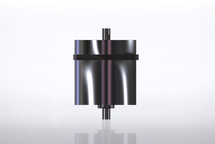
This is a Rotary Link Connector® capable of transmitting signals bidirectionally (3ch) between the stator side and rotor side at a maximum of 2 Mbps.
It is capable of non-contacting signal transmission, 5V/10W non-contacting power supply, and 360-degree continuous rotation communication with a rotating body.
This product facilitates connection between the rotating body and stator side, which used to pose problems, thereby eliminating design constraints. It also eliminates limits on the operating range, enabling previously impossible device designs and providing unlimited possibilities.
For example, the product can be used for data or electric power transmission to a rotating indicator light or for transmitting signals for controlling an electromagnetic valve, etc. on a rotating body.
![]()
| Interface | |
|---|---|
| High-speed data transmission 4ch | 3ch STATOR ⇁EROTOR |
| Power supply voltage | DC12V±5% |
| Performance | |
|---|---|
| Data transmission rate | -2Mbps/ch |
| Max. power supply | DC5V/10W |
| Mechanical features | |
|---|---|
| Rotation speed | <2000rpm |
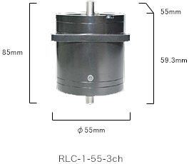
| Dimensions | ρE5mm L:59.3mm(excl. the center shaft) |
| Weight | Max.285g |
| Environmental features | |
|---|---|
| Temperature range | -20°C to +60°C |
| Vibration | 10Hz to 2KHz 147m/s² |
| Shock | 294m/s² 11ms |
![]()
| # | Color | Symbol | Description | Cablespec. |
|---|---|---|---|---|
| 1 | Brown | CH1a_IN | Signal Channel 1a Input | UL AWG30 |
| 2 | Red | CH2a_IN | Signal Channel 2a Input | UL AWG30 |
| 3 | Orange | CH3a_IN | Signal Channel 3a Input | UL AWG30 |
| 4 | Black | SG | Signal Ground 1a - 3a | UL AWG30 |
| 5 | Green | CH1b_OUT | Signal Channel 1b Output | UL AWG30 |
| 6 | Blue | CH2b_OUT | Signal Channel 2b Output | UL AWG30 |
| 7 | White | CH3b_OUT | Signal Channel 3b Output | UL AWG30 |
| 8 | Black | SG | Signal Ground 1b - 3b | UL AWG30 |
| 9 | Yellow | +12V_IN | +12V_Input | UL AWG28 |
| 10 | Black | GND | Power Ground | UL AWG28 |
| # | Color | Symbol | Description | Lead Wire |
|---|---|---|---|---|
| 1 | Brown | CH1a_OUT | Signal Channel 1a Output | UL AWG30 |
| 2 | Red | CH2a_OUT | Signal Channel 2a Output | UL AWG30 |
| 3 | Orange | CH3a_OUT | Signal Channel 3a Output | UL AWG30 |
| 4 | Black | SG | Signal Ground 1a - 3a | UL AWG30 |
| 5 | Green | CH1b_IN | Signal Channel 1b Input | UL AWG30 |
| 6 | Blue | CH2b_IN | Signal Channel 2b Input | UL AWG30 |
| 7 | White | CH3b_IN | Signal Channel 3b Input | UL AWG30 |
| 8 | Black | SG | Signal Ground 1b - 3b | UL AWG30 |
| 9 | Yellow | +12V_OUT | +12V_Output | UL AWG28 |
| 10 | Black | GND | Power Ground | UL AWG28 |
| # | Color | Symbol | Description | Lead Wire |
|---|---|---|---|---|
| 1 | Yellow | +12V_OUT | +12V_Output | UL AWG28 |
| 2 | Yellow | +12V_OUT | +12V_Output | UL AWG28 |
| 3 | Black | GND | Power Ground | UL AWG28 |
| 4 | Black | GND | Power Ground | UL AWG28 |